Close

GN 120.4
GN 120.4
Electromechanical Locking Systems
Plastic, for Latches
Plastic, for Latches
Specification
Specification
Identification no.
Identification no.
- No. 2: With latch arm check
Connection type
Connection type
- Type A: Connector plug (with 0.25 m cable)
Housing / Locking catch / Latch arm check
Housing / Locking catch / Latch arm check
Plastic, polyamide (PA)
- Glass fiber reinforced
- Black, RAL 9005, matte finish
Cable
Cable
Plastic, polyurethane (PUR)
Black
Plug
Plug
- Plastic, 8-pin, M12x1
- Knurled screw connection
- Brass, nickel plated
Operating temperature -20 °C to +60 °C
Operating temperature -20 °C to +60 °C
Information
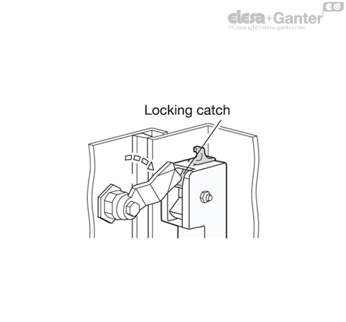
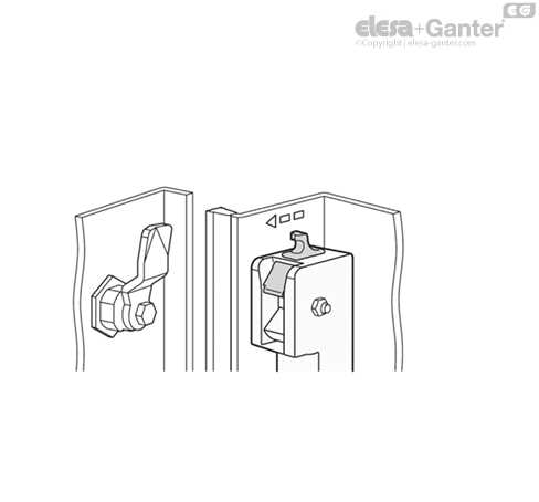
Electromechanical locking systems GN 120.4 are used together with latches GN 115 or GN 515. In the closed position, the latch arm is locked by the locking catch and by an electrical input signal. In addition, the presence of the latch arm in the closed position is detected and emitted as an output signal.
The locking system can be used for left or right locks and increases the latch distance A by 8 mm. Existing installations can be upgraded with minimal effort. The electromechanical locking system is also not visible from the outside.
Accessory
- GN 330 Cables with Connector Coupling
Technical information
Operation Description
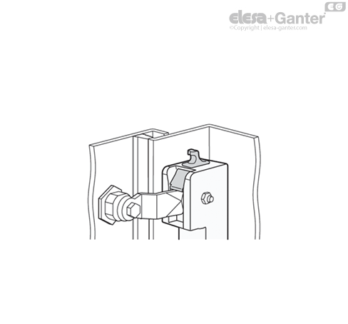
If the latch arm is moved to the closed position via the rotation limited to 90°, the spring-loaded locking catch snaps forward to prevent reopening of the latch.
In the closed position, the presence of the latch arm is detected by the latch arm check, and a high signal is output at the latch arm check output (pin 4) if a connection is also present between the additional contact pins 5 and 6. For example, this can take the form of a simple wire bridge or a door position check.
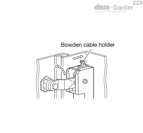
To release the latch again, a high signal is applied to control input pin 4, causing the locking catch to be withdrawn electromechanically. In the event of a power failure or system fault, the locking catch can be pushed back via the manual emergency release. The emergency release is designed to allow the fastening of a Bowden cable.
When the high signal at control input pin 4 falls away, the locking catch is released by the electromechanical mechanism, allowing the spring to push it forward again into the initial position.
Technical and Assembly Instructions
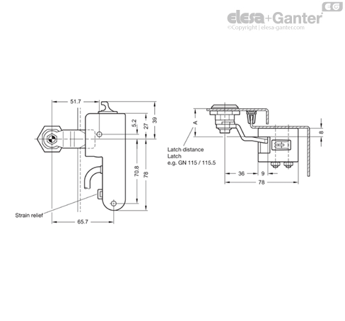
After installation, the connection cable can be additionally secured by a cable tie at the strain relief if necessary. The electromechanical locking system GN 120.4 can be easily added to existing installations. To accommodate the electromagnetic locking system, it is only necessary to increase the latch distance A of the latch by 8 mm. Corresponding latch arms are available for all typical latch distances.
Mechanical Features / Electrical Features / Approvals
| Mechanical Features | ||
| Fastening | 2x through-holes for M5 screws | |
| Recommended torque | max. 2 Nm | |
| Protection type | IP2x | acc. to EN 60529 |
| (observe cable protection!) | ||
| Emergency release | Fastening option for Bowden cable | |
| Electrical Features / Safety Features | ||
| Supply voltage | 12 - 24 VDC | |
| Max. power consumption | max. 120 mA; Stand-by 9mA | |
| Utilization category | DC 13: 24 VDC / 120 mA | acc. to EN 60947-5-1 |
| Contacts, connection type | 1 - Not used | |
| 2 - Supply voltage | ||
| 3 - Release control input | ||
| 4 - Latch arm check output | ||
| Plug M12x1, 8-pin, A-coded | 5 - Additional contact input | |
| 6 - Additional contact output | ||
| 7 - 0 VDC / functional grounding | ||
| 8 - Not used | ||
| Cable | 8 x 0.25 mm2, Li9Y11Y, jacket PUR, UL | acc. to IEC 60332-1-2 |
| Strain relief | With cable tie | |
| Short-circuit current | 1000 A | acc. to EN 60947-5-1 |
| Rated insulation voltage | 30 VDC | |
| Operating temperature | -20 °C ... +60 °C | |
| Degree of pollution, external | 2 | acc. to EN 60947-5-1 |
| Mission time (TM) | 20 years | acc. to EN ISO 13849-1 |
| Number of cycles (B10 d) | 50 000 | acc. to EN ISO 13849-1 |
| Approvals / Conformities / Applicability | |||
| CE marking | EN 61000-4-2 | ||
| EN 61000-4-3 | |||
| EN 61000-4-4 | |||
| UL Recognized | EN 61000-4-6 | ||
| EN 61000-4-8 | |||
Security Information
The information in the operating instruction must be observed during installation, initial operation, and use. It is enclosed with the product and is provided digitally on the product page at elesa-ganter.com.
The electromechanical locking system must be installed and commissioned by a qualified specialist in accordance with the information in the operating instructions as well as the national and international provisions and applicable standards.
Elesa+Ganter accepts no legal liability for missing or incorrect information or the consequences thereof.
/RedirectToProductView?storeId=10158&langId=-1&catalogId=11551&getCategoryPadre=true&=
Ask and we will answer as fast as possible
*Mandatory field
Your request was sent and will be answered as fast as possible.
Error
These products could be interesting for you as well