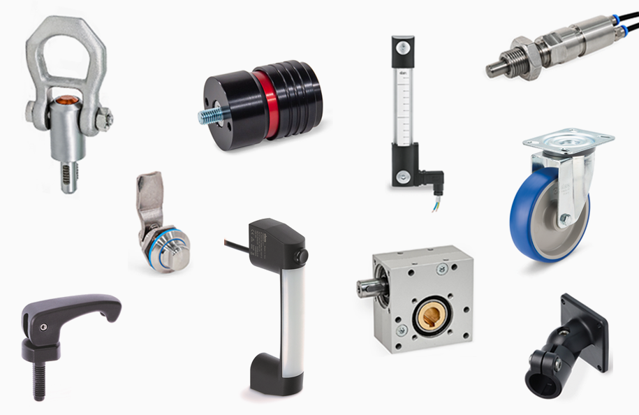
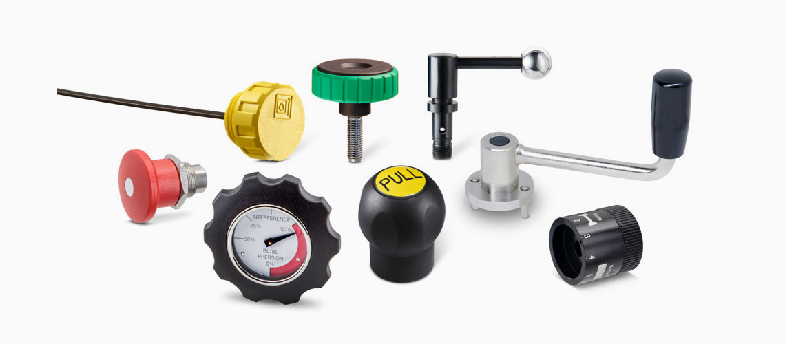
Specification
Types
- Type D: Pneumatically double-acting, protrude / retract
- Type A: Pneumatically single-acting, retract by spring force
- Type E: Pneumatically single-acting, protrude by spring force
Coding
- OP: Without position query
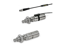
- BS0,4: Position query on both sides, with plug, cable 0.4 m
Stainless steel AISI 303
Plunger pin surface hardened
Rod seal
Polyurethane PUR
Piston seal and O-ring
Acrylonitrile butadiene rubber (NBR)
Magnet
Neodymium, iron, boron (NdFeB)
Polyamide (PA), black
Outer sheath polyurethane (PUR), black
Sensor clip
Polyacetal (POM), black
Hex nut ISO 8675
Stainless steel AISI 304
Information
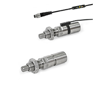
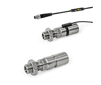
Indexing plungers GN 817.7 with pneumatic operation can be easily and securely integrated into automated processes and can be positioned at locations where hand operation of the indexing plunger is not possible. Thanks to the material used, the indexing plungers are also suitable for more aggressive environments.
An integrated magnet allows the plunger pin position to be queried electronically by a sensor. The end limits (protruding and retracted position) are taught-in via the operating element on the sensor cable. They each send a high signal, which is indicated by the respective LED and can be processed by a machine control, for example.
The sensor electronics can also be accessed via IO-Link and offer the ability to set and read out the switching points and to block the teach button on the operating element. To avoid interference, no external magnetic fields should act on the indexing plunger. The pneumatic indexing plungers are supplied with a lock nut. With coding BS0,4, the sensor, sensor clip and an allen wrench are also supplied loose.
Assembly Instructions
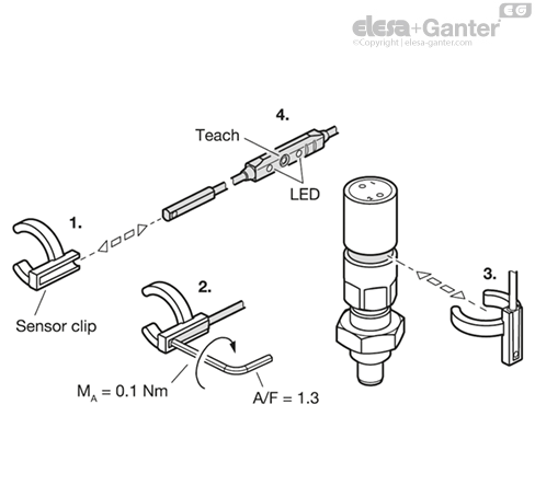
The radial position of the sensor cable can be freely determined when installing the sensor clip.
Installation steps:
1. Insert the sensor into the sensor clip from the side.
2. Tighten the hexagon socket screw of the sensor.
3. Clip the sensor clip into the ring groove of the indexing plunger and then adjust the position by turning, if necessary.
4. During commissioning, teach the sensor to the end positions via the operating element or IO-Link in accordance with the operating instructions supplied with the sensor.