Main specifications
Material
Cover: polyamide based (PA) technopolymer, black colour, matte finish. Graphic symbol "double valve".
Threaded connector: acetal based technopolymer (POM), black colour, matte finish.
Packing ring
NBR synthetic rubber.
Overpressure valve
Technopolymer with NBR synthetic rubber O-ring and stainless steel spring.
Set at around 0.350 bar (on request 0.700 bar).
Suction valve
Technopolymer sealing disk with NBR synthetic rubber O-ring and stainless steel spring.
Set at around 0.030 bar.
Ring-shaped air filter
"Tech-foam" polyurethane foam mesh (polyester base), air filtration 40 µ.
Fold-away key
CWL in acetal resin-based (POM) technopolymer, red colour, with stainless steel anti-intrusion-profile insert.
The key avoids the need for a torque limiter and allows the application of the manual screwing and unscrewing torque.
Also available with accessories sold separately.
Square key
CWQ in zinc-plated steel, the key allows the application of very high torques which make it impossible to unscrew by hand due to the intervention of the torque limiter.
Also available with accessories sold separately.
Maximum continuous working temperature
100°C.
"Vandal-proof" safety device (ELESA patent)
The vandal-proof device prevents unscrewing of the cap by unauthorised personnel as it is equipped with a “controlled-torque” torque limiter.
Standard executions
- SFW-VP: with CWL fold-away key.
- SFW-VP-CH: with CWQ square key.
General information
Applications
SFW-VP pressurised caps are suitable for earthworks and agricultural machinery, and in general for machinery that can be left unattended.
Features
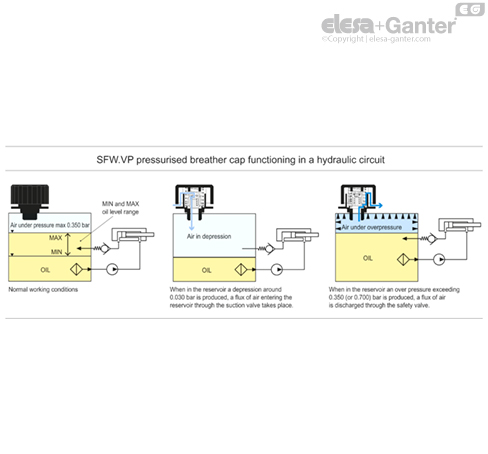
The use of SFW-VP pressurised breather cap which create a pressure plenum chamber right above the oil level within tested limit conditions, in order to avoid any reservoir deformation, offers also other advantages (see example of functioning in the SFW.).
Technical data
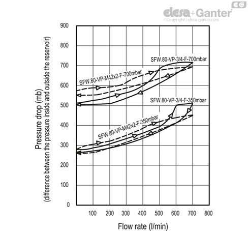
Air flow rate for the different executions of breather caps can be obtained from the diagram on the basis of the difference of air pressure inside and outside the reservoir.
Working in an hydraulic circuit
Other executions
Special executions on request
Caps with flat dipstick, flat section phosphatised steel.
Instructions of use
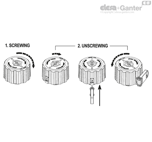
"Vandal-proof" safety device functioning
Screw the cap clockwise until the torque limiter clicks. For optimal tightening, it is advisable at this point to continue tightening with the key inserted: turn the cap cover clockwise until you reach one of the two points of resistance. Only in these two positions is it possible to fully insert the key to make the cover integral and to finish tightening.
Once the key has been removed, it is impossible to unscrew the cap, preventing any attempts at tampering (vandal-proof function).
Turn the cap clockwise until one of the two resistance points is reached. Only at one of these two positions the key, which couples the cover to the threaded connector, can be competely inserted and the cap can be unscrewed.