Close


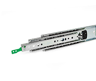
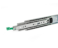
GN 1440-MR
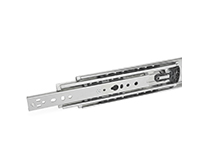
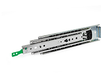
GN 1440
Telescopic Slides
Steel, with Full Extension, Load Capacity up to 3250 N
With rubber stop, latch in back, right
Steel, with Full Extension, Load Capacity up to 3250 N
With rubber stop, latch in back, right
Specification
InformationOn requestTechnical informationMounting Holes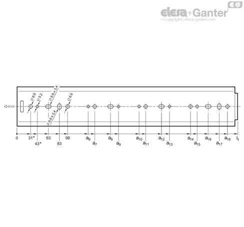
Specification
Types
Types
- Type B: With rubber stop
- Type MR: With rubber stop, latch in back, right
- Type ML: With rubber stop, latch in back, left
- Type K: With rubber stop, latch in front
- Type QR: With rubber stop, latch in back and in front, right
- Type QL: With rubber stop, latch in back and in front, left
Identification no.
Identification no.
- No. 1: Mounting with through holes
Slide profile
Slide profile
Steel
Zinc plated, blue passivated ZB
Bearings
Bearings
Roller bearing steel, hardened
Ball cage
Ball cage
Plastic
Latches
Latches
- Zinc die casting
- Plastic
Rubber stop
Rubber stop
Plastic
Operating temperature -20 °C to +100 °C
Operating temperature -20 °C to +100 °C
Information
Telescopic slides GN 1440 are installed vertically and in pairs. The stroke reaches ≈100 % of the nominal length l1 (full extension). Patented plastic ball cages ensure extremely smooth running of the slide.
Telescopic slides of various types, for example, with and without latch, can be combined freely, which is why GN 1440 is delivered as a single unit and not in pairs. Due to the symmetrical mechanical design, the types B and K can be mounted on either the left or right side of the extension.
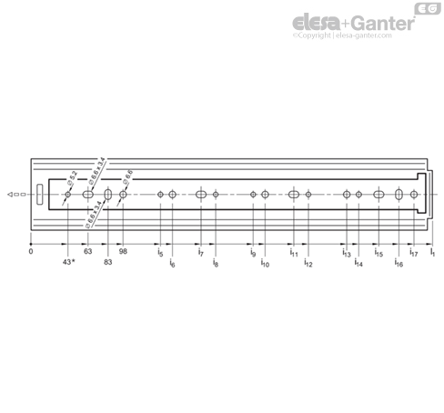
All mounting holes are easy to reach through auxiliary holes. Only the mounting holes are shown, but other production-related holes may be present.
On request
- Other lengths and hole spacing
- Other attachment options
- Other surfaces
Technical information
Mounting Holes
Mounting Holes - Outer Slide
| l1 | a6 | a7 | a8 | a9 | a10 | a11 | a12 | a13 | a14 | a15 | a16 | a17 | a18 |
| 300 | - | - | - | - | - | - | - | - | 161 | 173 | 193 | 213 | 228 |
| 400 | - | - | - | - | - | - | - | - | 261 | 273 | 293 | 313 | 328 |
| 500 | - | - | - | - | - | - | - | - | 361 | 373 | 393 | 413 | 428 |
| 600 | 213 | 228 | 363 | 378 | - | - | - | - | 461 | 473 | 493 | 513 | 528 |
| 700 | 213 | 228 | 363 | 378 | - | - | - | - | 561 | 573 | 593 | 613 | 628 |
| 800 | 313 | 328 | 463 | 478 | - | - | - | - | 661 | 673 | 693 | 713 | 728 |
| 900 | 313 | 328 | 463 | 478 | - | - | - | - | 761 | 773 | 793 | 813 | 828 |
| 1000 | 413 | 428 | 563 | 578 | - | - | - | - | 861 | 873 | 893 | 913 | 928 |
| 1200 | 313 | 328 | 463 | 478 | 713 | 728 | 863 | 878 | 1061 | 1073 | 1093 | 1113 | 1128 |
| 1500 | 413 | 428 | 563 | 578 | 913 | 928 | 1063 | 1078 | 1361 | 1373 | 1393 | 1413 | 1428 |
Mounting Holes - Inner Slide
| l1 | i5 | i6 | i7 | i8 | i9 | i10 | i11 | i12 | i13 | i14 | i15 | i16 | i17 |
| 300 | - | - | - | - | - | - | - | - | - | 173** | - | 213 | 228 |
| 400 | - | 161 | - | - | - | - | - | - | 261 | 273 | 293 | 313 | 328 |
| 500 | - | 229 | - | - | - | - | - | - | 361 | 373 | 393 | 413 | 428 |
| 600 | 213 | 228 | 398 | 413 | - | - | - | - | 461 | 473 | 493 | 513 | 528 |
| 700 | 313 | 328 | 463 | 478 | - | - | - | - | 561 | 573 | 593 | 613 | 628 |
| 800 | 313 | 328 | 498 | 513 | - | - | - | - | 661 | 673 | 693 | 713 | 728 |
| 900 | 413 | 428 | 563 | 578 | - | - | - | - | 761 | 773 | 793 | 813 | 828 |
| 1000 | 413 | 428 | 598 | 613 | - | - | - | - | 861 | 873 | 893 | 913 | 928 |
| 1200 | 313 | 328 | 463 | 478 | 713 | 728 | 863 | 878 | 1061 | 1073 | 1093 | 1113 | 1128 |
| 1500 | 413 | 428 | 563 | 578 | 913 | 928 | 1063 | 1078 | 1361 | 1373 | 1393 | 1413 | 1428 |
* The bore is only usable on types B and K. | ** The bore is only usable on types B, MR and ML.
Mounting Screws
For the said loading forces FS to be absorbed reliably in the surrounding structure, all available through-holes of the outer and inner slide having a diameter (Ø) of 6.6 must be used. Alternatively, holes with a diameter (Ø) of 5.2 are available. The elongated holes, Ø 6.6 x 3.4, facilitate adjustment during mounting when needed. Failure to use mounting screws reduces the load capacity. The following screws can be used for mounting:
| Designation - Standard | Outer slide | Inner slide |
| Hex socket button head screw | ISO 7380 | M 5 / M 6 | M 5 / M 6 |
| Hex socket low cylindrical head screw | DIN 7984 / DIN 6912 | M 5 | M 5 |
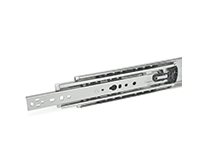
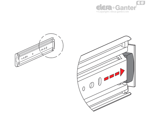
Type B with rubber stop
The rubber stops dampen the impact of the slide in the two respective end position. This feature minimizes noise development and increases the service life. Attached to the slides in a partially concealed, partially visible manner, the stops meet each of the requirements in regard to shape, material, and hardness.
If larger static or dynamic loads occur in the direction of extension, they should be absorbed by additional end stops.
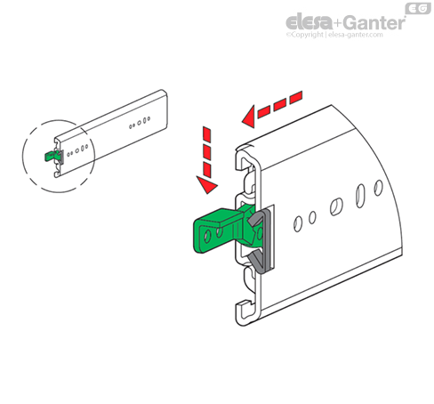
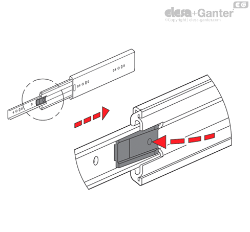
Types MR / ML with rubber stop, latch in retracted position
Types MR / ML are used in applications in which the slide needs to be locked in the back end position. This feature prevents the slide from extending on its own, for example due to an inclined position. If larger loads occur in the direction of extension in the latched position, they should be absorbed by additional latch elements.
When closed, the latch mechanism locks into place under spring load via a recess on the outer rail. Pressing the release lever releases the inner and middle slide for extension. Back in the retracted position, the mechanism automatically locks into place again via the recess on the outer slides by moving over a ramp.
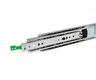
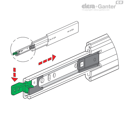
Type K with rubber stop, latch in extended position
Type K is used when the extension is to remain in the extended position for a certain amount of time. This feature allows maintenance work to be performed with the slide being extended, for example. If larger loads occur in the latched position, they should be absorbed by additional latch elements.
For the function to be activated, the slide has to be fully extended to the front, where it will automatically lock into place via a pretensioned latching lever. Pressing the lever releases the slide, allowing slide to retract again.
Types QR / QL with rubber stop, latch in extended and retracted position
Types QR / QL combine the features of types MR, ML and K. The inner and middle slide lock into place in the two end positions.
In contrast to the locking of type K, types QR / QL are operated via an internal linkage. Pressing the green release lever activates the locking rocker, releasing the slide rail for retraction or extension.
/RedirectToProductView?storeId=10158&langId=-1&catalogId=11551&getCategoryPadre=true&=
Ask and we will answer as fast as possible
*Mandatory field
Your request was sent and will be answered as fast as possible.
Error
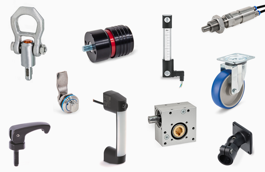
These products could be interesting for you as well