Specification
Version in Zinc Die Casting
Types
- Type DK: With triangular spindle
- Type VK7: With square spindle
- Type VK8: With square spindle
- Type VDE: With double bit
- Type SCK: With wing knob (same lock)
- Type SCT: With T-Handle (same lock)
- Type RG: With knurled knob GN 7336
Lock housing
Zinc die casting ZD
Housing collar
Powder coated
Black, RAL 9005, textured finish SW
Operating elements
Plastic (Polyamide PA)
Black, matte finish
Key
Nickel silver with plastic hand piece
Cover cap (Type RG, KG, HG)
Plastic (Polyamide PA)
Light gray, matte finish
Other parts
Steel, zinc plated, blue passivated
Version in Stainless Steel
Types
- Type DK: With triangular spindle
- Type VK7: With square spindle
- Type VK8: With square spindle
- Type VDE: With double bit
- Type RG: With plastic knurled knob GN 7336
- Type KG: With wing plastic knob
- Type HG: With plastic lever
- Type SG: With stainless steel star knob
- Type KGN: With stainless steel wing knob
- Type HGN: With stainless steel lever
Lock housing
Stainless steel NI
Latch arm
Stainless steel AISI 304
Stainless steel AISI 304
Sheet metal drawn and hub welded
Stainless steel AISI CF-8
Plastic (Polyamide PA)
Black, matte finish
Other parts
Stainless steel AISI 303 (Types DK, VK7, VK8, SCH, VDE)
Stainless steel AISI 304 (Types RG, KG, HG, SG, KGN, HGN)
Information
Latches GN 515 are identical to standard latches GN 115 except for the extended housing. They are operated with a rotation limited to 90°, which moves the latch arm into the locked position behind the frame. The bevels of the latch arm ease the closing of the door. Thanks to the stainless steel material, the latches are optimally suited for use in corrosive environments.
By installing latch arms (zinc die casting version) with different bend profiles, the latch distance A can be varied from 16 to 92 mm depending on the housing height h1, while the extended housing is suitable for a door thickness s up to 50 mm.
By installing latch arms (stainless steel version) with different bend profiles, the latch distance A can be varied from 18 to 82 mm depending on the housing height h1, while the extended housing is suitable for a door thickness s up to 40 mm.
The latches (with operating elements, lockable) each come with 2 keys and loosely enclosed latch arm. The key can be removed in both end positions. The lock is standard, so that every lock can be opened with the same key.
Latches GN 515 (except types SCK, SCT) are supplied with loosely enclosed latch arm.
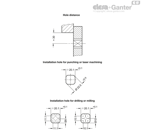
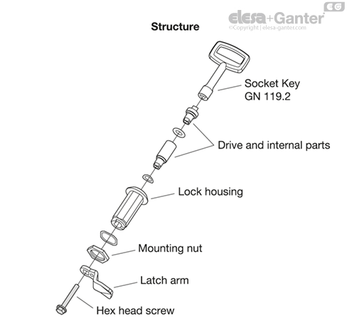
Construction and Assembly Instructions
For installation, set a hole in the door, cover or hatch as shown in the outline drawing.
The required installation hole in the door leaf, is usually generated by punching or laser machining in series production.
The installation hole diameter can also be created by drilling or milling as shown in the outline drawings.
When mounting the latches, care should be taken to ensure that the internal parts of the latch do not fall out of the housing when removing or mounting the hex head screw.