Close


Download
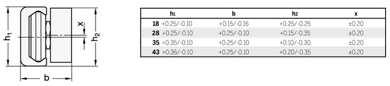
Tolerance for mounted linear guide rail systems
In the combination of rails GN 2422 (see page 654) and cam roller carriages GN 2424 (see page 656), the following dimensions / tolerances exist.
If several cam roller carriages are installed into one rail, an offset x can occur between the cam roller carriages which must be added to the dimension h2.
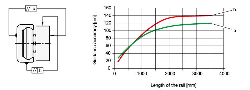
Guidance accuracy
Linear guide rail systems feature the linear guidance accuracy shown in the diagram.
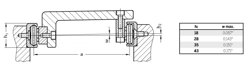
Permissible height offset
The fixed and floating bearing principle ensures that misalignments in the base construction are compensated. However, when using Type UV / UT and XV / XT rails, certain limits should not be exceeded. The following table shows the maximum permissible angle of the height offset of the fixed and floating bearing rails. Please note that the load rating must be reduced by 30% once the specified value is reached.
To calculate h2, the following equation should be used: h2 = a x tan w, with the tabular values shown below used for w.
Example: h1 = 43, a = 650 mm, w max. = 0,171° h2 = 650 mm x tan 0,171° = 1,94 mm
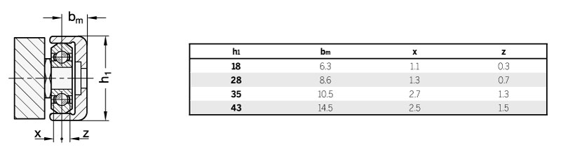
Permissible lateral offset
It is possible to compensate for angular defects and the offset of the mounting surface with the help of fixed and floating bearing rails. The permissible offset of cam rollers and cam roller carriages in the Type UT / UV rails is given by the values for x and z. The reference is the nominal middle of the raceway bm.
A parallelism or angular error can thus be compensated for across the whole length of the rail, which corresponds to an offset from the sum of the values for x and z.
Support widths
To guarantee the proper running motion, outside dimensions must be observed during the assembly of linear guide rail systems. Suitable components include supports at the rail and at the roller carriage which should not be smaller than the widths a or b. Also, forces acting from the outside can thus be transferred reliably from the linear guide rail systems without submitting the mounting screw to shear stress.

Tightening torque
When positioning the rails with countersunk mounting holes, Type UT and XT, make sure the surface is flat and the mating tapped holes are tapped deep enough so the flat head screw is flush with the rail.
The specified tightening torque of the flat head screws must be maintained.

Traversal speed
Depending on application and installation length, the maximum traversal speed of cam roller linear guide rail systems is 7 m/s.
Lubrication
Once the cam roller carriage has been placed in the rail, it is recommended to slightly grease the raceway surfaces of the rail with a heavy duty lubricant for linear guide rail systems, such as Klüberplex BE 31-222, using a brush.
Check the lubricant film at regular intervals for any dirt or pollution, e.g. with metal chips.
In the event of visible pollution or clear discoloration of the lubricant, use a clean rag to clean the rails and the rollers and apply new lubricant.
Applying new lubricant is normally necessary once a year or after 100 km of running distance.
Operational temperatures
The components of the roller guide systems are suitable for use in a temperature range of -30 °C to 130 °C.
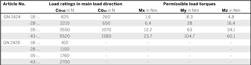
Load rating
The installation space, the desired mode of attachment and the load to be carried are the determining factors when selecting the best possible roller guide system. The values given below will help in selecting the most suitable cam roller carriage or the most suitable cam rollers.
The details on load capacity are non-binding guide values given without liability and does not constitute any type of guarantee or warranty of intended use. The user must determine in each individual case whether a product is suitable for the intended application. Environmental factors and aging may affect the stated values.

Linear guide rail systems consist of a cam roller linear guide rail GN 2422 (see page 654) and a cam roller carriage GN 2424 (see page 656). All components are packed separately and supplied not assembled. When delivered, the play between cam roller carriage and rail is not preset.
During assembly, set the cam roller carriage as follows:
1. Make sure that the raceways and the cam rollers are clean.
2. Slightly loosen the mounting screw of the central, eccentrically adjustable roller and insert the cam roller carriage (without the wipers supplied) into the rail (see also items 4 and 6).
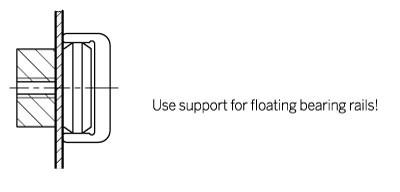
3. Position the cam roller carriage at one end of the rail. For the floating bearing rails of Type UT and UV, a thin and stable support (e.g. open-end wrench or a feeler gauge) must be placed underneath the ends of the cam roller carriage body and the rail to ensure the parallel alignment of the cam roller carriage in the level raceways.
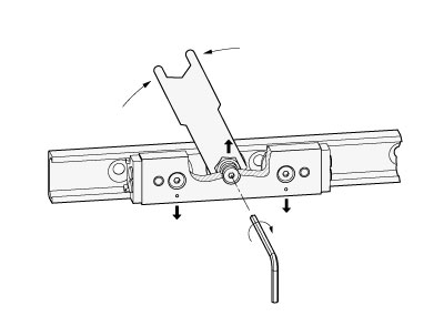
4. Insert the open-end wrench GN 2424.1 (included) (see page 656) between the eccentric cam roller and the cam roller carriage body. (The centering bores to the left and right mark the position of the running side of the concentric cam rollers / load-bearing cam rollers.)
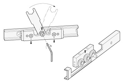
5. Turning the open-end wrench clockwise will press the cam roller to be adjusted against the top raceway which will set the roller carriage free of play. Excessive pre-tensioning must be avoided because this will increase friction and reduce useful service life.
6. While using the open-end wrench to hold the bearing pivot in the correct position, the mounting screw may be moderately tightened. The correct tightening torque will be checked later.
7. Move the cam roller carriage in the rail and make sure that the play / the moderate pre-tensioning is constant along the full length of the rail. The running motion should be free-moving, with the cam roller carriage having any play or jamming at no point inside the rail.
8. Now tighten the mounting screw with the recommended tightening torque shown in the table, with the open-end wrench holding the angular position of the cam rollers in place.

9. Now mount the wipers, and for cam rollers carriage type N, the longitudinal seal. To do so, remove the cam roller carriage from the rail.
10. Before reinserting the cam roller carriage, make sure that the raceways / rollers are properly lubricated using a heavy duty lubricant for linear guidance.