Close


Download
When selecting a suitable linear slide, it is primarily the available space, the desired stroke and the load carried which must be taken into consideration. The values listed below are intended as guidelines for selecting the most suitable nominal rail size.
The details on load rating are non-binding guide values given without liability and does not constitute any type of guarantee or warranty of its intended use. The user must determine in each individual case whether a product is suitable for the intended application. Environmental factors and aging may affect the stated values.
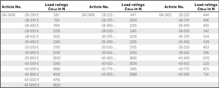
No details on the permissible load torques are given for the telescopic linear slides as these are normally used for paired applications. Loads of these dimensions occur to a minor degree because it may be assumed that the surrounding construction has sufficient rigidity and stiffness. Transferring load torques within certain limited is permitted.
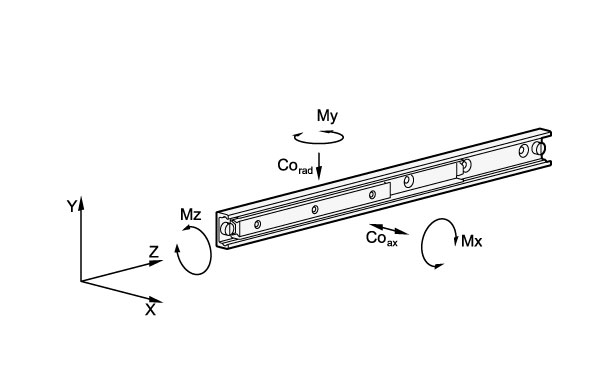
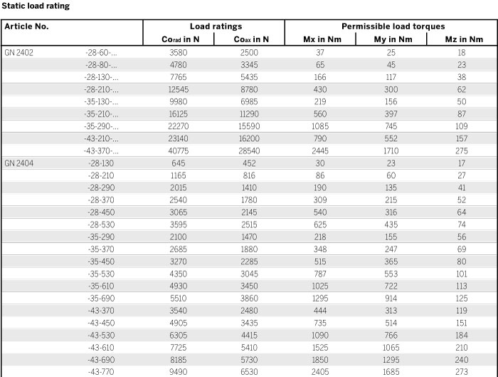
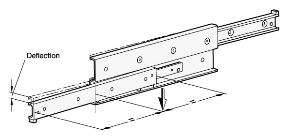
Static load and deflection
The load values given in the tables refer to a maximum permissible force allowed to act in the middle of the fully extended profile rail at the third segment. If the given values are observed and if the telescopic linear slide is fully extended, a minor deflection (sag) occurs at the end of the runner or of the rail. This has normally no detrimental effect on the proper function of the application. If required, guide values may be given if requested.
Mounting screws, assignment of the mounting holes
The standard mounting hardware is DIN 7991-10.9 countersunk head screws, to be mounted with the recommended tightening torque. Depending on type, not all mounting holes may be utilized. In general, these holes can be left unused. In exceptional cases, especially in bilateral stroke, mounting holes can be accessed by loosening the support screws and by pulling out the runner. The support screws are then put back in place.
Traversal speed, cage slip
The traversal speed in linear slides can be as much as 0.8 m/s. The particular application and the installation length can have an effect on this value. In the event of rapid changes of direction and high accelerating forces, cage slip may occur in some cases, especially in long ball cages. In cases such as these, the cage does not move synchronously with half the speed of the runner, but gradually loses its correct position owing to the slip. Whenever possible, running a blank stroke to the end of the traversal distance should be provided for back positioning.
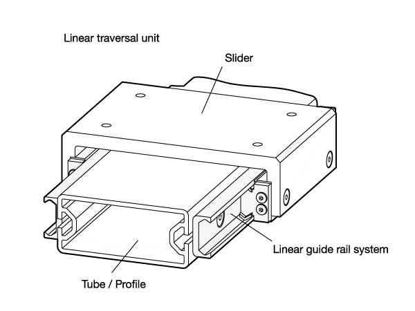
Linear guide rail systems allow the reliable and economical linear movement of hardware modules. Their outstanding attributes are low-maintenance operation, long service life and quiet running. These are attributes which make roller guide systems indispensable components for efficient and safe movement of devices, and meet the needs of facilities with low energy requirements.
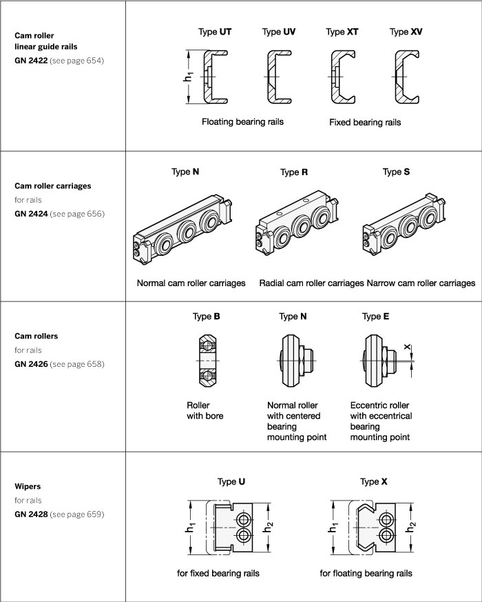
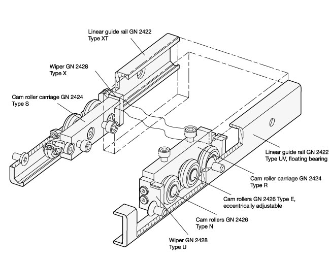
The product range includes all components necessary for constructing linear guide rail systems that are compact and easy to assemble and install. All inear guide rail systems consist of one outer rail with rollers or roller carriages moving inside the rail.
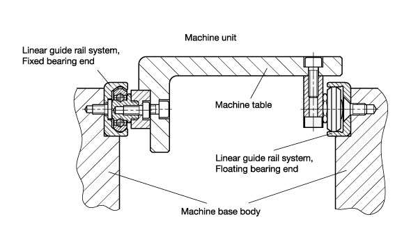
Rails are the foundations for linear guide rail systems. They can be constructed as fixed or floating bearing versions, with the fixed bearing type guiding the rollers running inside the rail on two levels, while the floating bearing type does so only on one level. By combining both versions, any misalignments or parallelism errors in the connected construction can be corrected. Complex preliminary work caused by the precision machining of surrounding parts can thus be kept to a minimum. Both rail versions can be mounted in one of two ways: cylindrical countersunk holes, or 90° conical holes for self-centering.
Cam roller carriages are available in 3 different types of designs, differing by their radial or axial assembly arrangement, their material, and their degree of sealing. All cam roller carriages consist of 3 rollers, with the middle one always supplied with an eccentrically adjustable bearing pivot for determining the initial tension or the clearance/play inside the rail. Depending on the rail version, a wiper is mounted on either end of the roller carriage.
Cam rollers are similar in structure to deep-groove ball bearings, with a non-detachable bearing pivot used as mounting point.
For special applications, cam rollers and wipers can also be supplied separately from the cam roller carriages under separate standards.
All design variants are available in the nominal rail dimensions h1= 18, 28, 35 and 43 mm. Beyond the standard range, they can also be supplied in lengths of up to 3600 mm in one piece, or as combined rails for individual and customized requirements.
To insure maximum flexibility, linear guide rail systems are made from the components listed below. Depending on the requirement, the appropriate components can be supplied in the desired quantity. Because the linear guide rails and the cam roller carriages must be assembled separately in many applications, these items will be supplied unassembled and packed separately.
Upon request, fully pre-assembled linear guide rail systems including rails GN 2422 and cam roller carriages GN 2424 are available.